Kirchhoff's Laws · Loop Voltage and Node Current
DC circuit (dual mesh) | Adjust any resistor value and observe that KVL and KCL always hold
\(U_1 = 12\text{V}\) (fixed) | Three loops · Four resistors · Two mesh currents
Circuit Parameter Settings
Fixed voltage source in the left-hand branch
Circuit Structure Diagram
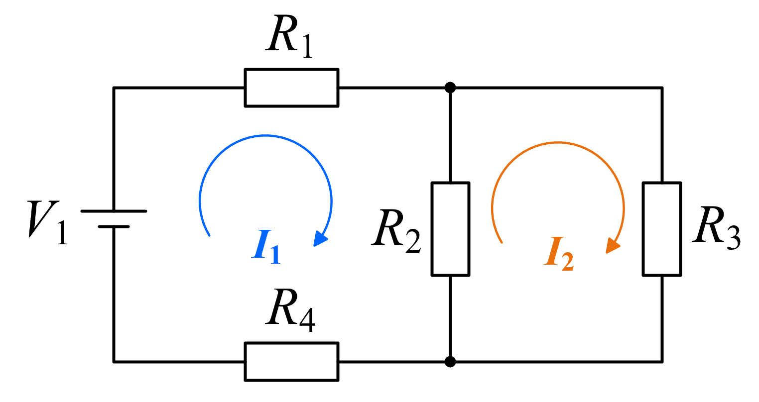
Branch currents: \(I_{R1}=I_1,\; I_{R4}=I_1,\; I_{R2}=I_1-I_2,\; I_{R3}=I_2\)
Branch Voltage Distribution · Bar Chart
Current Calculation Results
KVL & KCL Verification
Kirchhoff's Voltage Law (KVL)
\(\sum V = 0\) Around any closed loop, the algebraic sum of voltage rises equals the algebraic sum of voltage drops. Regardless of how component parameters change, KVL always holds strictly. This simulation demonstrates KVL verification for 3 loops: left loop (\(U_1\)-\(R_1\)-\(R_2\)-\(R_4\)), right loop (\(R_2\)-\(R_3\)), and outer loop (\(U_1\)-\(R_1\)-\(R_3\)-\(R_4\)).
Kirchhoff's Current Law (KCL)
\(\sum I = 0\) At any node, the total current flowing into the node equals the total current flowing out. In this circuit, at the top middle node B: \(I_{R1}\) (inflow) = \(I_{R2} + I_{R3}\) (outflow). KCL always holds exactly. Adjusting any resistor value verifies this relationship.