Superposition Theorem: Decomposition and Synthesis of Multi-Source Linear Circuits
Linear circuit with voltage source \(U_s\) and current source \(I_s\) | Individual contributions | Superposition verification \(U_{out} = U_{out1} + U_{out2}\)
Circuit Parameters
Analysis View
Output Voltage \(U_{out}\) (Voltage between a and b)
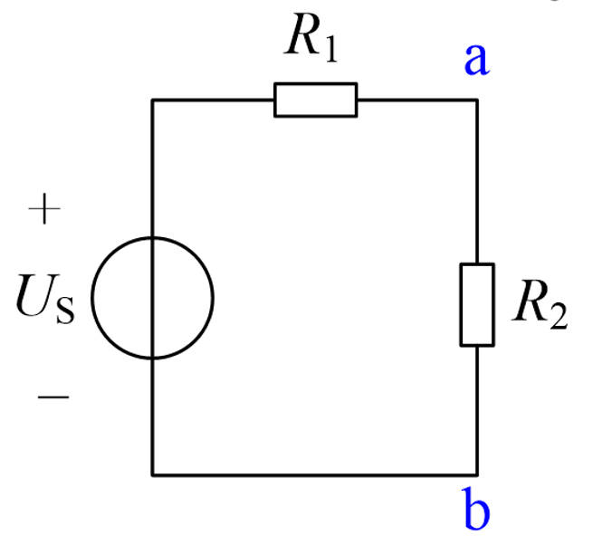
\(U_s\) acting alone
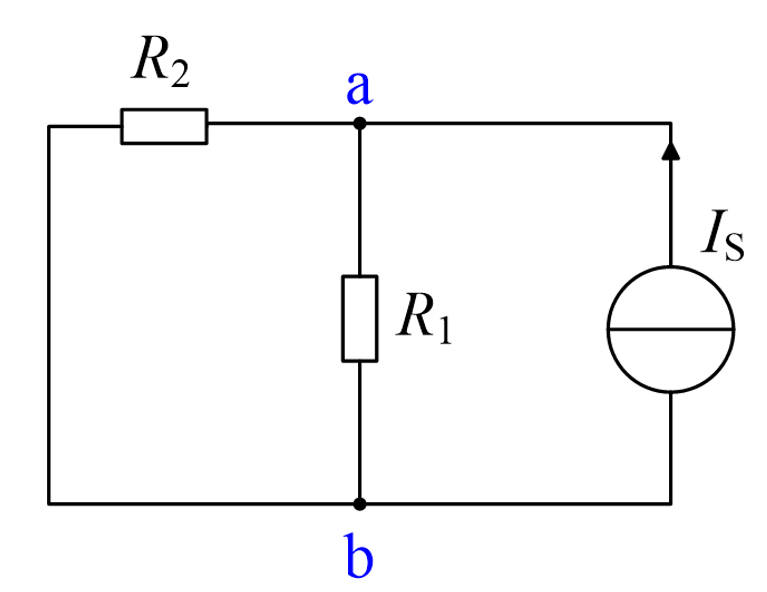
\(I_s\) acting alone
Complete Circuit (Superposition)
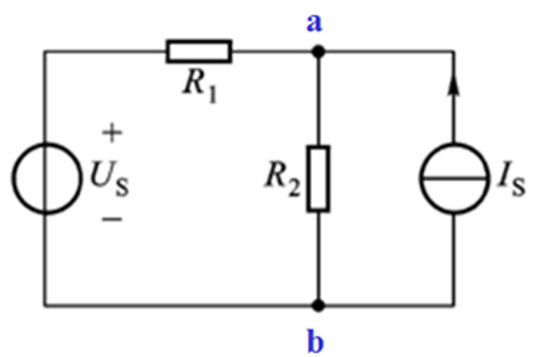
Output voltage \(U_{out}\) (Voltage between a and b)
Theoretical Basis
In a linear circuit, the response (voltage or current) at any point equals the sum of the responses produced by each independent source acting alone.
When \(U_s\) acts alone, \(I_s\) is open-circuited; when \(I_s\) acts alone, \(U_s\) is short-circuited.
\(U_{out1} = U_s \cdot \frac{R_2}{R1 + R_2}\)
\(U_{out2} = I_s \cdot (R_1 \parallel R_2)\)
Superposition Properties
Zeroing a voltage source -> replace with a short circuit (wire).
Zeroing a current source -> replace with an open circuit (disconnection).
The superposition theorem applies only to linear circuits (linear resistors, linear dependent sources, independent sources).
Power cannot be directly superposed (since power is a quadratic function of voltage/current).