Thevenin & Norton Equivalent Theorems: Two-Terminal Network Simplification
Active two-terminal network → Thevenin or Norton equivalent → connect the same load \(R_L\) and verify identical terminal voltage and current
Circuit Parameters
Equivalent Parameters
Equivalence Verification (Load \(R_L\))
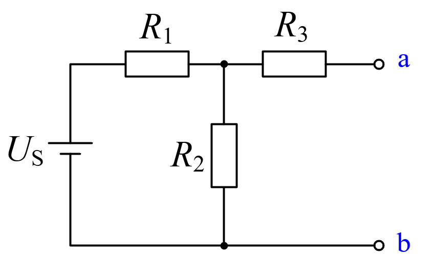
Original Circuit Topology
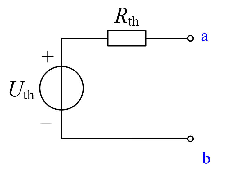
Thevenin Equivalent Circuit
Theoretical Basis
Any two-terminal network composed of linear elements and independent sources can be replaced, from the perspective of an external load, by a voltage source in series with a resistance (Thevenin) or a current source in parallel with a resistance (Norton).
\(U_{th} = U_s \cdot \frac{R_2}{R_1+R_2}\), \(R_{th} = R_3 + \frac{R_1 R_2}{R_1+R_2}\), \(I_N = U_{th}/R_{th}\).
Equivalence Properties
Regardless of the load \(R_L\) connected, the original circuit and the equivalent circuit have identical V-I characteristics at the a-b terminals.
Thevenin and Norton forms are duals: \(U_{th} = I_N \cdot R_{th}\), \(R_{th} = R_N\).
Adjust the sliders to observe that both sides always match, verifying the equivalence theorem.